Learn the Torque Cutting Edge ISO Code
In this article, what is ISO Code? How to read iso code for inserts? What are insert iso codes? What are the torne cutting iso codes? You will find solutions to your questions like these.
1. Insert Shape
The shape of a turning insert is determined by the 1st part of the ISO code.

It is very important to choose the correct cutting edge shape for your turning tool. The shape of the cutting edge can affect the vibration during operation, the ability to turn complex contours, the power of the cutting edge, and the ability to take on larger and heavier cuts.
You can see the shape options for the Turning Inserts and how they are related to their ISO code below.
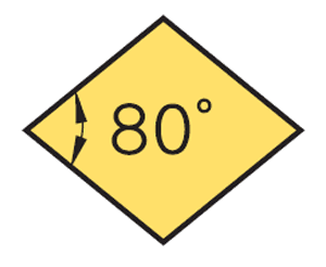
C. Elmas 80° (Rhombic)
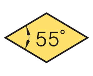
D. Diamond 55° (Rhombic)
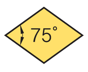
E. Elmas 75° (Rhombic)
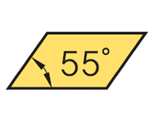
K. Parallelogram 55°

L. Rectangle 90°

Mr. Round

S. Square 90°
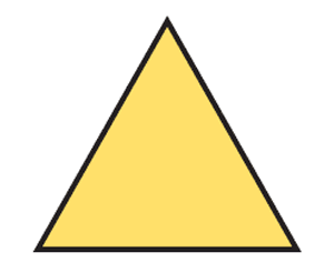
T. Triangle 60°
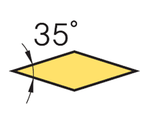
Diamond V. Elmas 35° (Rhombus)
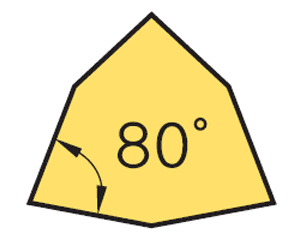
W. Trigon 80°
2. Approach Angle
The relief angle of a turning tool is determined by the 2nd part of the ISO code.

Relief angle is the angle between the cutting edge and the workpiece. The relief angles on cutting edges can be Positive or Negative. Negative cutting edges will always have a 0° relief angle, but there will still be some clearance between the workpiece; this will be set by the angle at which the cutting edge sits on its holder. A positive cutting edge will have a relief angle of approximately 1-30°, so a positive cutting edge generally has only 2 cutting edges while a negative cutting edge has 4 cutting edges.
See below for options for embossing angles and how they relate to their ISO code.

B. 5°

D. 15°

F. 25°

Page 11°

C. 7°

E. 20°

North 0°

O. Special Type
3. Tolerance
The tolerance of a turning insert is determined by the 3rd section of the ISO code.

Tolerance dimensions are indicated with a letter ranging from A to U. Dimension A is related to the written diameter (IC), dimension B is related to the cutting edge height (for pentagon, triangle, and trigon shapes - for other polygons, dimension B is related to the distance measured along the bisector of the corner angle), and dimension T is related to the thickness of the cutting edge.
See below for tolerance options and how it relates to its ISO code


d: Described as a flat
t: Thickness
m: Indicates the figure
(mm)
C, E, H, M, O. P, R, S, T, W Additive Shape Tolerance (Exception)
D Cutter Tip Tolerance (Exceptional Case)


* Dimensions are with respect to unground cutting edge
4. Section Type
The cross-section type of a lathe cutting tool is determined by section 4 of the ISO code.

The cut emphasizes differences such as fixation holes, shanks, and special features in the design of the cutting tool. This determines which attachment method will be used to fix the cutting tool to the tool holder.
See below for options for cross-section type and how it relates to its ISO code.

5. Cutting Edge Length / Inner Diameter IC
The cutting edge length of a turning insert is determined by the 5th section of the ISO code.

It is usually a two-digit number that shows the width or length, but this is only valid for shapes that do not include IC (written circle) such as rectangles and parallelograms.
For such cutting edge shapes as round, square, triangle, and trigon, this indicates the diameter of the written circle (IC).
Refer to the options for Cutting Edge Length / IC Diameter below and how it relates to its ISO code

6th Thickness
The thickness of a turning insert is determined by the 6th section of the ISO code.

The thickness of a turning insert is measured from the underside of the cutting edge to the top of the cutting edge. Except in cases where the cutting edge contains a T followed by a single digit, this will be shown as a two-digit number, for example, T3. This is because there are multiple increments within each mm, for example, 03 is 3.18 mm while T3 is the thickest at 3.97 mm.
You can see the options for cutting insert thickness and how they are related to the ISO code below.

O. Special Type

O. Special Type

O. Special Type

O. Special Type

7th Angle
The nose radius of a turning insert is determined by section 7 of the ISO code.

A cutting tool's nose radius can affect performance. A larger nose radius can lead to higher feed rates and greater cutting depths, and can withstand more pressure, making them much better for heavier metal removal. On the other hand, a lathe cutting tool with a smaller nose radius can only take smaller cutting depths, also having weaker cutting edges, and can only withstand a small amount of vibration. However, they are much better for finishing due to being sharper and having less surface contact.
You can see the options for the radius of the chamfering tool and how it is related to its ISO code below.

8th Chip Breaker Symbol
The turning tool for boring bars is determined by position 8 in the ISO code.

Chip breaker is represented as a 2-letter code in ISO. The chip breaker affects the cutting resistance, if the cutting resistance is low, it can prevent the edge of the cutting from crumbling and breaking. Reduced cutting resistance can also reduce tool load and resulting heat. The chip breaker also determines the cutting depth the cutting edge can take, if you do not apply the correct cutting depth, you will not activate the chip breaker, which can cause the chips to accumulate and become fibrous, some people call this a bird's nest.
Each currency has its own chip break symbol.
This page has been taken from cutwel.co.uk and translated into Turkish. ↗️
Author: Tom Beaumont